Today we explore the application of the actual circuit work of the inductor, in the actual circuit is mainly the use of inductors through the low-frequency resistance to high-frequency, through the DC resistance to AC characteristics of the design of different circuits, the following we take a look at the inductor in the DC-DC boost circuit principle of operation.
1. Switch S is closed:
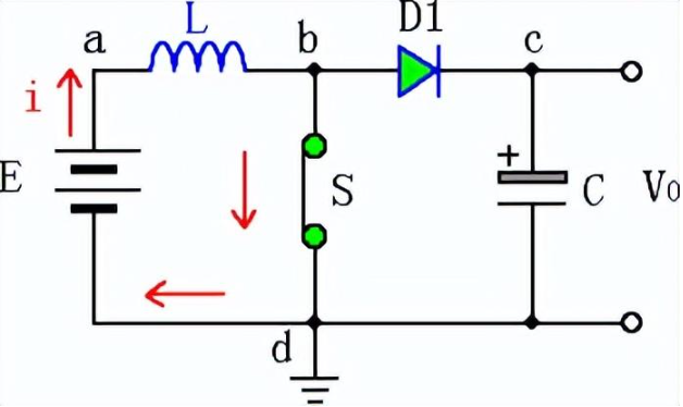
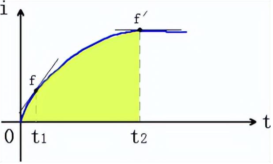
As shown in Figure 1, when the switch S is closed, a, b, d constitute a closed loop, the power supply E through the inductor produces a small to large current i, at this time t1 (such as Figure 2 t1 → t2) current frequency tends to be close to the high-frequency, according to corrugator’s law (increase anti-decrease the same), the inductor produces induced current in the direction of the opposite direction of the original current i, induced current impedes the change in the i, inductor induced current direction of the b → a, which means that the power supply current i in the inductor into magnetic energy stored until t2 when the current i is the largest, the obstruction force is also the largest, the magnetic energy stored in the inductor is also the largest. Then t2 after the current tends to smooth, the current frequency tends to DC, the inductor obstruction is weakened, the excess current through the switch, the composition of the closed loop flows to the negative pole.You can explore similar components from our All product List for use in DC-DC circuits.
2. Switch S disconnect:
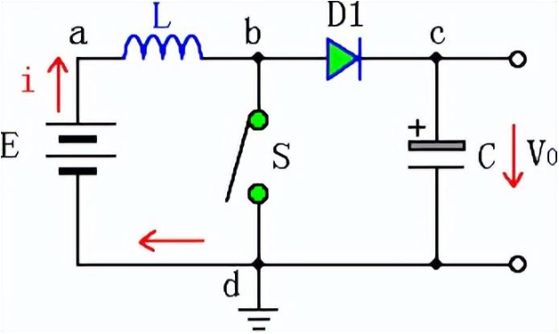
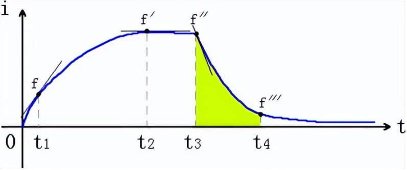
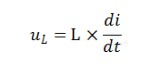
As shown in Figure 3, when the switch S is disconnected, a, b, d does not constitute a closed loop, the power supply E flows through the inductor current instantly from large to large i, at this time t3 (as in Figure 4 t3 → t4) current frequency tends to be close to the high-frequency, according to corrugator’s law (increase anti-decrease the same), the inductor produces an inductive current in the direction of the same direction as the original current i, induced current impedes i change, the direction of the inductor induced current for the a → b, which means that power supply Current i in the inductor will have turned the magnetic energy began to be converted to current, the direction of the current through the diode a → b → c → d, i.e., the voltage at point b for the inductor induced electromotive force e plus the original power supply voltage E, they are together through the diode D1 to the capacitance C charging stored, and at the same time, the output voltage to the load U0, if you do not take into account the diode’s voltage drop, U0 = E + e. which induced the voltage can be expressed by the size of the A formula: This formula indicates that the induced voltage size and inductance size, the rate of change of current per unit time can be explored further at our New Center for technical insights.
So at this time the voltage U0 is higher than the supply voltage E. Until t2 when the current i is the smallest, the obstruction force is also the smallest, the magnetic energy stored in the inductor is also basically fast conversion end. Next, through the switch constantly closed, disconnected, you can constantly output voltage U0, and the voltage U0 is higher than the supply voltage E, so as to play the purpose of boosting.
3. Switch into a field effect tube:
Post time: Sep-11-2024