
Planar vs. Wirewound Transformers — A Practical Selection Guide for Power Engineers
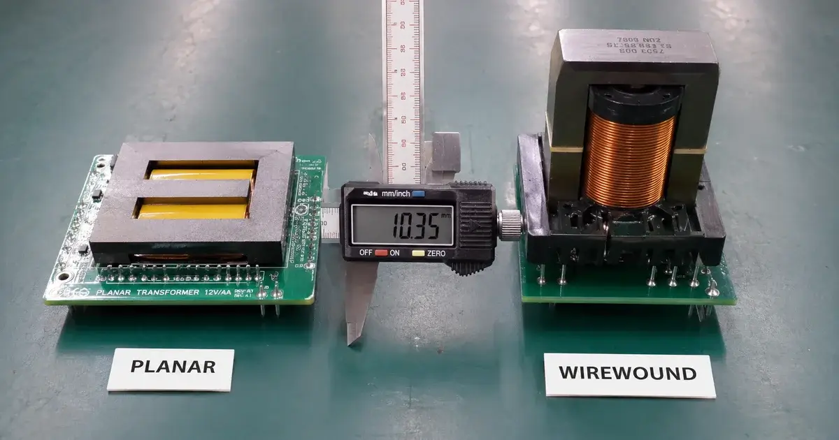
1. The Wrong Question
Ask most engineers “planar or wirewound?” and they’ll tell you planar is for high frequency, wirewound is for high power.
That’s not wrong, but it misses the point. The real question is not which technology is better — it’s which constraints your design has.
If your primary constraint is height (< 15mm), planar wins. If your primary constraint is cost per unit, wirewound wins. For everything else, it depends.
This guide walks through both technologies from a practical engineering perspective: what they can do, what they can’t, and how to decide without spending two weeks prototyping the wrong approach.
2. What Each Technology Actually Is
A quick structural comparison before we get into performance:
| Aspect | Planar Transformer | Wirewound Transformer |
| Winding | PCB traces (embedded or multilayer) | Copper wire wound on bobbin |
| Core | Low-profile E/ER/I core pairs (PQ, EEL, EFD) | Standard E, EE, EF, PQ, RM cores |
| Assembly | PCB layers + core sandwich, soldered | Automatic winding machine + termination |
| Typical height range | 6–15mm | 12–35mm |
| Typical frequency | 200kHz – 2MHz | 50kHz – 500kHz |
| Typical power range | 50W – 2kW | 10W – 10kW+ |
| Parasitic control | Very good (low leakage, predictable) | Moderate (leakage depends on winding technique) |
The mechanical construction difference drives every other characteristic. Once you understand that, the performance differences make sense.
3. Eight-Dimension Performance Comparison
| Dimension | Planar | Wirewound | Why It Matters |
| Leakage inductance | 0.1–0.5% of Lm | 0.5–3% of Lm | Lower leakage reduces snubber loss and voltage spikes |
| Inter-winding capacitance | Higher (50–200pF) | Lower (10–50pF) | High capacitance creates common-mode noise issues |
| Winding height | 0.5–2mm (PCB layer) | 5–20mm (bobbin) | Directly drives overall transformer height |
| DC resistance | Higher (thin PCB traces) | Lower (thick wire) | Higher DCR = higher I²R loss in high-current designs |
| Thermal conduction | Good (PCB copper spreads heat) | Poor (wire-to-core thermal resistance) | Planar dissipates heat through PCB plane more evenly |
| Current per winding | Limited by PCB copper thickness | Flexible (choose wire gauge) | Planar is constrained to 2–4 oz copper typically |
| Turns ratio flexibility | Limited by PCB layer count | Very flexible | Odd turns ratios or many taps are easier with wire |
| Tooling / NRE cost | Higher (PCB + custom core) | Lower (standard core + bobbin) | Planar becomes cost-effective only at volume |
Each row in this table is a trade-off. The engineering decision is about which trade-offs your design can tolerate.
4. Where Planar Transformers Struggle
Planar transformers are not a universal upgrade. They solve certain problems and create others.
Multilayer winding loss. A planar transformer’s winding is made of PCB copper traces. At high frequency, skin and proximity effects concentrate current in the outer layers. If you use an 8-layer PCB for a 1:8 turns ratio, the inner layers carry almost no current at 500kHz — the effective resistance is much higher than the DC value suggests. This is called the “layer stack penalty,” and it limits planar transformers to roughly 4–6 effective layers for high-frequency designs.
Limited copper thickness. Standard PCB copper is 1 oz (35µm). Even with 2 oz or 4 oz, the trace cross-section is small compared to a 0.5mm magnet wire. For designs above 10A RMS per winding, planar transformers require either interleaved parallel layers (which multiplies the layer count) or external copper posts.
Cost vs. volume. A planar transformer requires a custom PCB footprint, a custom core (usually non-standard shape with low profile), and sometimes a custom bus bar for high-current windings. The NRE can be 3–5× higher than a wirewound design. At low volume (< 10,000 units/year), the per-unit cost is almost always higher.
Turns ratio limitations. A 1:3.7 turns ratio is easy with wire (count 37 turns on secondary, 10 on primary). With planar, you’re limited to integer ratios defined by PCB layer count. This forces compromises in the converter duty cycle or voltage stress.
5. Where Wirewound Transformers Struggle
Wirewound transformers have been around for decades. Their limitations are well known, but worth repeating for selection purposes.
Leakage inductance is a design headache. In a standard bobbin-based transformer, leakage inductance is typically 1–3% of magnetizing inductance. This creates voltage spikes on the primary switch at turn-off, requiring snubbers, higher-voltage MOSFETs, or both. Interleaving (splitting primary between secondary sections) reduces leakage but increases assembly complexity and cost.
Height is fixed by bobbin dimensions. A standard EE19 bobbin is about 12mm tall. An RM10 is about 18mm. If your enclosure height limit is 10mm, most bobbins won’t fit — you need a custom low-profile bobbin, at which point the cost advantage over planar disappears.
Parasitic repeatability. Wirewound transformers have higher unit-to-unit variation in leakage and capacitance than planar transformers. The winding tension, wire placement, and tape application all vary slightly. For production volumes where consistent switching behavior matters, this variation adds design margin that reduces efficiency.
6. Decision Framework — Which One Should You Use?
| Primary Constraint | Recommended | Why |
| Height < 12mm | Planar | Wirewound bobbins rarely fit under 12mm |
| > 15A RMS per winding | Wirewound | PCB copper can’t carry it without excessive loss |
| Frequency > 800kHz | Planar | Core loss dominates; planar core geometry reduces loss |
| Prototype quantity < 100 pcs | Wirewound | Planar NRE (PCB + core tooling) is too high for small runs |
| Need precise leakage control | Planar | ±10% tolerance vs. ±30% for wirewound |
| Multiple output windings | Wirewound | Adding windings just means more pins; planar needs more PCB layers |
| Cost-sensitive, high volume | Wirewound (optimized design) | Standard cores + automated winding are hard to beat at scale |
| Low profile + high current | Both (hybrid) | Planar for primary + copper foil or bus bar for secondary |
The hybrid option is worth mentioning. Many high-density power supplies use a planar primary winding (low leakage, predictable) with a copper foil or wire-wound secondary (carries high current). This combines the best of both approaches at the cost of a more complex assembly process.
7. FAQ — Quick Answers
Q: Is a planar transformer more efficient than a wirewound transformer?
Not inherently. Planar transformers have lower leakage (reducing switching loss) but higher winding AC resistance (increasing copper loss). The net efficiency depends on the operating frequency and duty cycle. At 500kHz+, planar often wins. At 100kHz, wirewound is typically more efficient.
Q: Can I replace a wirewound transformer with a planar one in an existing design?
Not without redesigning the PCB footprint, core clamp, and possibly the controller loop compensation. The leakage inductance and capacitance are different enough to change the switching behavior.
Q: Why are planar transformers more expensive?
Custom PCB + custom core (non-standard shape) + higher NRE. Standard wirewound cores are manufactured in volumes of millions, driving cost down. Planar cores are niche.
Q: What’s the maximum power a planar transformer can handle?
Commercially available planar designs typically go up to 2–3kW. Beyond that, wirewound or litz-wire approaches are more practical due to current handling limits.
Q: Do planar transformers require special PCB materials?
High-frequency designs (1MHz+) may benefit from high-frequency laminates (Rogers, Megtron) which increase cost. For 200–500kHz, standard FR-4 is usually sufficient if the layer count is managed.
Q: Can you make a prototype planar transformer quickly?
The PCB fabrication lead time is the bottleneck — typically 5–10 days for prototype quantities. Core procurement adds 1–3 days if the core is in stock. Total lead time is around 1–2 weeks, similar to custom wirewound samples.
📌 Need fast turnaround? See how Linkpower delivers transformer samples in 24 hours.*
Q: Which is better for automotive applications?
Both are used. Wirewound dominates for onboard charger and DC-DC converter applications above 1kW. Planar is popular in auxiliary power modules where height is constrained.
📌 For automotive requirements, see our IATF 16949 guide.*
8. Bottom Line
Planar and wirewound transformers are not competing technologies. They’re tools for different constraints.
Height-constrained, high-frequency, precision-critical designs lean planar. Cost-sensitive, high-current, flexible-ratio designs lean wirewound. The overlap zone (100–500kHz, 100W–1kW, 12–18mm height) is where the real engineering judgment matters.
If you’re in that overlap zone and want an experienced second opinion on which approach fits your design, send us your requirements.
📌 Need help writing your transformer specification? Our RFQ guide covers what information to include.*

Please Contact Us