Why Power Supply Engineers Don’t Pay Attention to Transformer DCR (And Why They Should)
1. The “Ref.” Nobody Reads
Open any transformer datasheet. Find the DC resistance row. You’ll see something like this:
| Parameter | Value | Note |
| DCR (primary) | 0.15Ω | Ref. |
| DCR (secondary) | 0.008Ω | Ref. |
That “Ref.” means reference only. The manufacturer isn’t committing to anything.
Most engineers read inductance, turns ratio, saturation current, then stop. DCR gets skipped because “Ref.” sounds like it doesn’t matter.
Here’s the problem: in a 50A-output power supply, that secondary DCR of 8mΩ becomes a real loss. 50² × 0.008 = 20W of heat, just in the winding. If you ignored DCR during selection, you designed that heat in without accounting for it.
2. Why DCR Gets Ignored — and When It Actually Matters
Three reasons engineers skip DCR:
- Datasheets say “Ref.” — the manufacturer explicitly avoids committing, so designers assume it’s not a spec.
- In low-current designs it truly doesn’t matter. A 1A flyback transformer with 1Ω DCR loses 1W total. Nobody cares.
- Transformer vendors never volunteer DCR control. If you don’t ask, they don’t offer — and the quote stays cheaper.
DCR becomes critical in exactly one situation: high current, low voltage output. That’s GPU power, server VRM, battery formation equipment, and low-voltage high-current DC-DC converters.
Here’s why. Copper loss is I²R. Double the current, quadruple the loss. A transformer winding carrying 30A with 5mΩ DCR loses 4.5W. At 60A it’s 18W — four times more.
Low-voltage outputs are worse because the loss is a bigger fraction of the delivered power. A 48V output losing 5W is noise. A 1.2V output losing 5W is 4% of the entire output budget gone.
| Output Voltage | Output Current | DCR Loss | % of Output Power |
| 48V | 2A | 0.008W | negligible |
| 12V | 10A | 0.08W | 0.07% |
| 3.3V | 30A | 2.7W | 2.7% |
| 1.2V | 50A | 20W | 33% (before regulation) |
The last row is the killer. At 1.2V/50A, secondary DCR of 8mΩ dissipates 20W — and that’s just one winding.
3. The Real Cost of DCR — It Compounds
DCR doesn’t just cost static efficiency. It triggers a feedback loop:
1. Copper loss heats the winding.
2. Copper’s resistance rises with temperature — about 0.39%/°C.
3. Higher resistance means more copper loss at the same current.
4. More loss means more heat. The loop continues until thermal equilibrium.
This is why a transformer that “runs fine at 25°C” fails at 85°C ambient. At 85°C, DCR is roughly 23% higher than at 25°C (60°C rise × 0.39%/°C). The thermal runaway margin you thought you had was never there.
The compounding effect in numbers:
| Ambient | Winding Temp | DCR Multiplier | Loss at 50A (8mΩ base) |
| 25°C | 25°C | 1.00× | 20W |
| 50°C | 70°C | 1.18× | 23.5W |
| 85°C | 110°C | 1.33× | 26.6W |
A 33% increase in copper loss you didn’t budget for — purely because DCR was “Ref.”
4. Why Transformer DCR Is Harder to Control Than Inductor DCR
Inductors are easy: one winding, few turns, tight DCR tolerance achievable.
Transformers are not. Here’s what makes transformer DCR inherently harder to control:
- More turns. A 1:10 transformer has 11 windings’ worth of wire. Each turn adds variance.
- Layer count. Multi-layer windings have different effective lengths per layer — outer layers are longer.
- Wire tension during winding. Loose tension = longer effective wire = higher DCR. Tight tension risks insulation damage.
- Termination method. Solder vs. weld vs. crimp all add different contact resistance.
- Secondary paralleling. High-current secondaries often parallel multiple strands — each strand’s length must match, or current sharing suffers.
A realistic DCR tolerance for a production transformer is ±10% to ±15% — compared to ±5% to ±8% for a well-made inductor.
That’s precisely why vendors mark it “Ref.” They know they can’t hit a tight tolerance without raising cost, so they avoid the commitment.
5. How to Spec DCR Properly
You can absolutely get DCR controlled — you just have to ask for it the right way.
Don’t write: “DCR: as low as possible.”
Do write:
| Requirement | Value |
| DCR (primary, 25°C) | 0.15Ω max |
| DCR (secondary, 25°C) | 8mΩ max |
| Test condition | Kelvin (4-wire) measurement, 25°C ± 2°C |
| Sampling | Per lot, n=5, all must pass |
| Temperature note | DCR measured at 25°C; derating per copper coefficient |
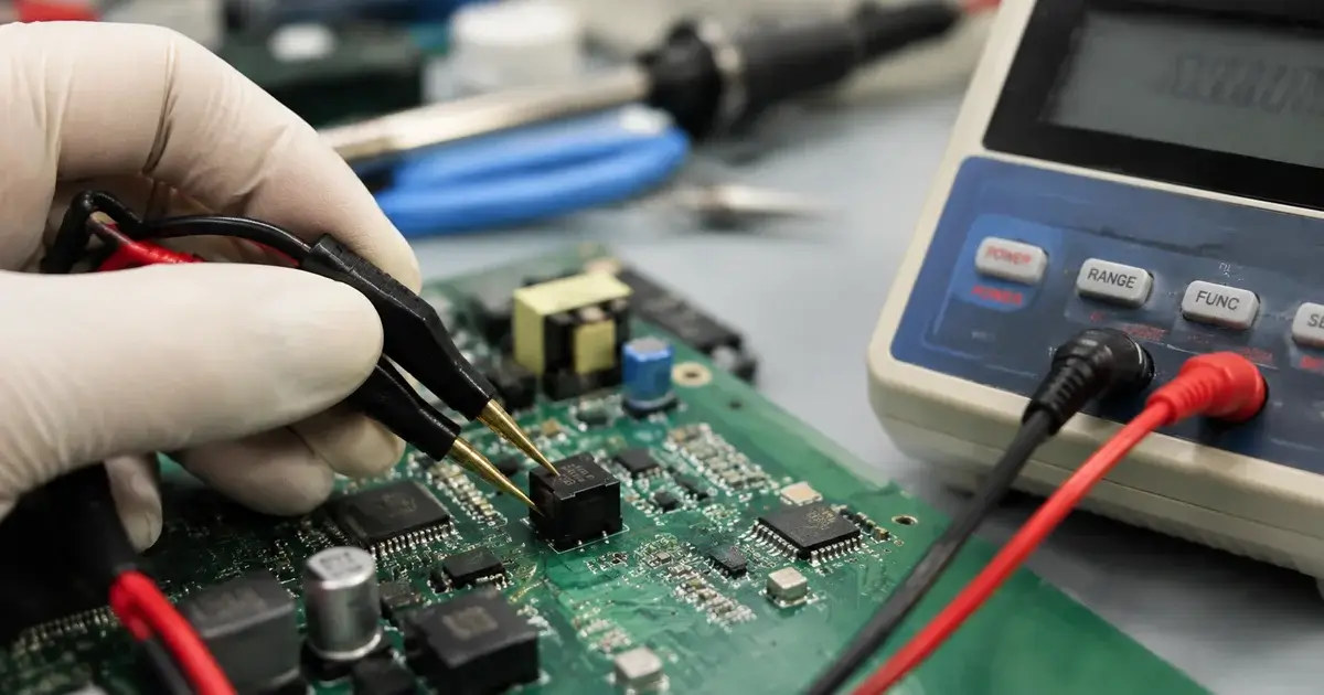
And verify it yourself. When you receive samples, measure DCR with a 4-wire milliohm meter — not a handheld multimeter, which reads contact resistance as part of the measurement. A 10mΩ reading on a handheld meter can be 3mΩ of contact resistance + 7mΩ of true DCR.
Also ask the vendor for the DCR spec on the sample test report, not just the datasheet. Our sample reports include measured L, DCR, turns ratio, and Hi-Pot — the actual numbers, not pass/fail marks.
📌 For details on what a proper transformer specification includes, see our RFQ guide for custom transformers.*
6. FAQ — Quick Answers
Q: What is DCR in a transformer?
DC resistance — the resistance of the copper winding measured with DC current. It’s the primary source of copper loss (I²R) in magnetic components.
Q: Why do transformer datasheets mark DCR as “Ref.”?
Because DCR tolerance is hard to hold in production (±10-15% typical) and vendors don’t want to commit to values they might exceed. It’s a business decision, not a technical necessity.
Q: Does DCR affect transformer efficiency?
Yes. Copper loss = I²R. At high current, DCR loss dominates and can exceed core loss by 3-5×.
Q: How do I measure transformer DCR accurately?
Use a 4-wire (Kelvin) milliohm meter. Two-wire multimeters include lead and contact resistance, which can be larger than the DCR you’re measuring.
Q: What’s a good DCR value for a high-current transformer?
It depends on current. A practical target: DCR × max current² ≤ 1-2% of output power. For a 50A secondary, that means DCR under ~5-8mΩ.
Q: Does DCR change with temperature?
Yes. Copper resistance rises ~0.39%/°C. At 85°C (110°C winding), DCR is ~33% higher than at 25°C.
Q: Can a transformer vendor control DCR in production?
Yes, if you spec it. Require a maximum value with 4-wire measurement and lot sampling. Vendors who do this are rare — which is why most mark it “Ref.”
📌 Want samples with measured DCR data on the test report? See how we deliver transformer samples in 24 hours.*
7. Bottom Line
DCR is the most ignored parameter in transformer selection — and the one that costs you the most in high-current designs.
It’s not a fixed property. It drifts with temperature, varies lot to lot, and compounds into efficiency and thermal problems you never see coming.
Stop accepting “Ref.” Start writing DCR as a spec: maximum value, 4-wire measurement, 25°C reference, per-lot sampling. And measure it yourself on samples before you commit.
If you’re designing a high-current power supply and want transformers with real DCR control — send us your spec. We’ll give you measured numbers on the sample report, not a “Ref.”

Please Contact Us